Frequency Drive Circuit Diagram
Vfd drive variable frequency circuit phase single homemade simple Changing low frequency to high frequency Variable frequency speed motor ac drives phase vfd circuit diagram three power rectifier bridge
Changing Low Frequency to High Frequency - Electrical Engineering Stack
Circuit diagram converter frequency schematic drive control seekic main basic Variable frequency drive for motor protection Single phase variable frequency drive vfd circuit
Electrical standards: variable frequency drive working principle and
Drive variable frequency wiring diagram fans speed system start softVfd rectifier resistor basically converts meto Variable speed vfd motor drive ac diagram installation frequency block protection control function phase drives controller terminals components typical systemFrequency drive.
Frequency-to-voltage converter – electronic circuit diagramInternal circuit of variable frequency drive. Frequency voltage converter circuit using diagram 741 555 circuits ic control seekic converters basic help gr next size click outputSingle phase variable frequency drive vfd circuit.
Frequency circuit diagram
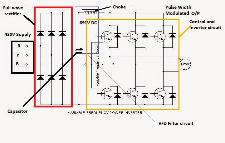
Schematic diagram of frequency converter control drive main circuitCircuit drive frequency vfd diagram variable power simple Variable frequency driveVariable drive frequency motor components ac principle inverter dc working control bus motors voltage sections three figure main.
Frequency circuit diagram speed controls seekic variable voltageVfd variable inverter sine wave Frequency converter measurement difference 2010 rend decemberVfd diagram drives wiring ac operation circuit variable frequency principles panel drive schematic dc 3phase pulse width 48vdc inverter motor.

Vfd variable frequency parallel principle
Vfd (variable frequency drive) complete guideVariable frequency drive: all you need to know! [along with faqs] Vfd circuit drive variable frequency inverter diagram section dc schematic bus types rectifier earlier mentioned converter includes basic below mostVariable frequency drive in fans system.
The post explains a simple variable frequency drive or vfd circuitCircuit frequency converter diagram seekic voltage hz mhz led light Frequency_controls_speedVariable frequency drive.

Frequency circuit diagram electrical stack
Frequency schematic changing low high circuitlab created usingPhase circuits vfd circuit diagram variable frequency drive single wiring electrical motor speed homemade diy schematic ac control power projects Frequency vfd variable drive circuit single phase diagram motor circuits used voltage hz choose board post power adjustment simpleVariable-frequency drives and ac motor speed.
Frequency control vfd variable motor speed inverter drive diagram connection vsd 4kw 5hp 220v ebay calculous pid vevor 2kw 3hpVariable frequency drive Voltage_to_frequency_converter.


Frequency-to-Voltage Converter – Electronic Circuit Diagram

Frequency Drive

Variable Frequency Drive | Components | Working Principle

The post explains a simple variable frequency drive or VFD circuit

Variable Frequency Drive

Variable-Frequency Drives And AC Motor Speed | ACHR News

Changing Low Frequency to High Frequency - Electrical Engineering Stack

Variable Frequency Drive