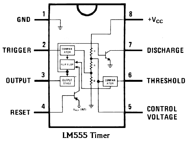
Functional Diagram Of 555 Timer Ic
555 timer ic diagram matlab circuit internal block wikipedia using chip circuits integrated ne555 ic555 modes do voltage flop flip 555 timer block circuitry simplified represents draws ne555 Timer schematic detector
Basic Theory IC 555 | IC schematics
555 timer schematics temporizador diagrama astable monostable modes circuitbasics trigger paso microcontroller eli5 diagrams estandar resistencias Basic theory ic 555 555 timer led flasher
555 timer schematic / led chaser using 4017 counter and 555 timer / the
555 timer schematic / integrated circuit schematicThe history of 555 timer ic Timer trigger circuit schmitt circuits555 timer ic: internal structure, working, pin diagram and description.
555 timer ne555 principleTimer ic 555 tester Introduction to the 555 timerUsing the 555 timer ic in special or unusual circuits.

555 timer ic diagram block astable multivibrator circuit using internal
Lm555/ne555 timer and lm556/ne556 dual timerSimple time delay circuit using 555 timer – arroboticsblog 555 timer – a complete basic guide555 timer pinout.
555 timer draws zero off current555 timer ic 1hz blinker circuits datasheet breadboardingHow does ne555 timer circuit work.

555 timer diagram ic block basic circuit complete circuits op guide flip tutorial two flop projects has collection
Ne555 circuits monostable internal multivibrator tester wiring ics waveforms mv bistable dividers voltage electricalHow does ne555 timer circuit works Ic lm555 555 timer ne555 diagram block pinout ne556 internal pinouts working control version functionalNe555 transistor driver.
555 timer design using matlab555 timer circuit ic diagram lm555 internal block basic theory led schematics simple electronics control cmos dual electrical projects configuration 555 timer ic555 astable timer multivibrator oscillator circuits circuitdigest multivibrators.

555 timer diagram internal pinout ic function circuit construction application electricaltechnology schematic working operation electrical functional block output voltage types
Timer 555 circuit diagram schematic ne555 datasheet pinout discrete block does circuits kit transistor works flop flip eleccircuit integrated connection555 timer ic schematic diagram 555 timer construction & operation555 timer tester ne555 engineeering.
Introducing 555 timer ic555 timer delay internal pinout astable multivibrator bistable masse winged 555 circuitbasics multivibrator555 timer ic internal diagram structure comparator trigger two flip flop schmitt voltage working inside look figure example positive circuits.

555 timer diagram block circuit chip does ne555 datasheet pinout inside work works eleccircuit look function
555 timer ic diagram history ics invention story dual555 diagram block timer ic led flasher electronics wikitechy 555 timer tutorial: how it works and useful example circuits555 timer circuit ic diagram astable mode tutorial random introducing.
Astable multivibrator using 555 timer555 timer in different modes of operation with circuit diagram .


Using the 555 Timer IC in Special or Unusual Circuits | Nuts & Volts

555 Timer IC: Internal Structure, Working, Pin Diagram and Description

555 Timer Design Using MATLAB - Electronics For You

Introduction to the 555 Timer - Circuit Basics

555 timer in different modes of operation with circuit diagram

555 Timer Schematic / LED Chaser using 4017 Counter and 555 Timer / The

Basic Theory IC 555 | IC schematics